A sensor has 16 bytes ready to encrypt. The key is loaded, but the consumer of the ciphertext is busy. Can the core finish anyway? Yes, provided it can keep the ciphertext safe from the next input until delivery.
The design has two jobs. AES determines the ciphertext’s value; the interface determines which rising edge accepts input and when output transfers. Correct arithmetic alone cannot prevent a lost or duplicated transaction.
This guide builds an AES-128 encryption-only iterative core: one block in flight, one round per cycle. Follow data through the circuit, arrange timing, then debug against known answers. You need XOR, combinational logic, registers and nonblocking assignments. The snippets are not a complete compilable IP. AES specifies transformations; our timing and handshake rules are architecture choices.
For the encryption concepts first, read the AES Comic Classroom.
1. What AES-128 processes
AES-128 takes a 128-bit plaintext block and a 128-bit key and produces a 128-bit ciphertext block. It applies an initial key XOR followed by ten rounds. The “128” names the key length; all AES variants use 128-bit blocks.

Read the block as sixteen bytes, B0 through B15. For the hexadecimal input 00112233445566778899aabbccddeeff, B0 is 00 and B15 is ff.
The big picture: follow one block through the IP
Put yourself in the system designer’s position. A processor or sensor supplies data; your AES IP is the hardware module responsible for encryption. The surrounding system wants to hand over a plaintext block and later collect its ciphertext. It does not need to know how you built the S-box, but it does need to know when a transfer is allowed.
Start with three cooperating areas. This view describes responsibilities, not individual RTL wires. Learn the roles before memorizing module names.
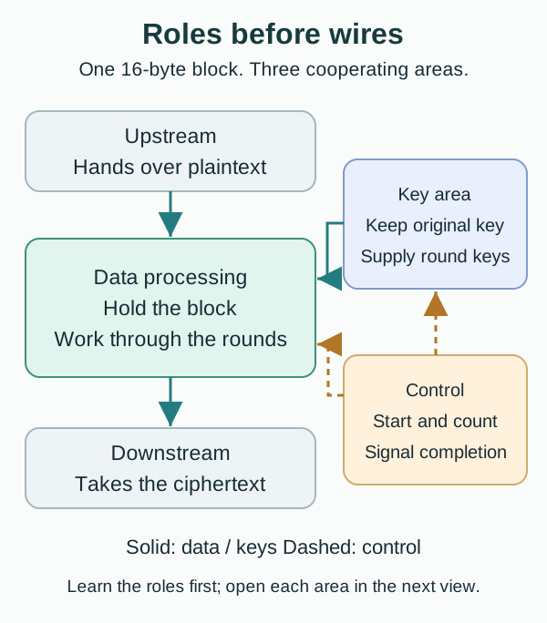
The datapath answers “what calculation?” It holds the sixteen bytes, applies AES transformations, and saves the intermediate result after each round. SubBytes, ShiftRows, MixColumns and AddRoundKey will become parts of this path.
The key area answers “which key for this round?” The external system provides one original key, but AES uses round keys derived from it. These are not fresh random passwords. The upstream system does not have to send a new key every cycle: the key-expansion circuit computes them according to a fixed rule.
The controller answers “when?” It remembers whether the core is waiting for input, processing a particular round, or waiting for output acceptance. It does not perform the S-box substitutions or XORs. It selects the operation, decides when registers update, and signals when the result is valid.
Walk through a complete transaction
Assume the key is already loaded. Upstream offers a block and the core indicates that it can accept it. At the agreed rising edge, the transfer happens and the core captures the sixteen bytes in its own register. Upstream may then change its input. Without that capture, later calculations could accidentally use upstream’s next block.
The core performs the initial AddRoundKey, then ten rounds. In each round the datapath reads the current intermediate value, the key area supplies the appropriate key, and control arranges the next register update. An intermediate value is not ciphertext ready for delivery. Its apparently scrambled appearance is no reason to assert out_valid early.
After the final round, the core announces that the result is valid. If downstream is busy, the ciphertext stays in the register until downstream accepts it. Computation completion and transaction completion can therefore happen at different times. The valid/ready signals in section 14 express this agreement electrically.
Do ten rounds require ten copies of the circuit?
No. Think of one workbench: finish a step, put its result back on the bench, then use the same tools for the next step. An iterative architecture reuses one round circuit while feeding its results back through storage.
An alternative is to unroll multiple round circuits. With suitable pipeline registers, different blocks can occupy different stages at the same time. That costs more hardware and requires additional timing and control design. For a first implementation, one reused circuit makes it easier to track a single block and compare each round with a reference.
Keep two concepts separate: a round is a unit of algorithmic work; a cycle is the time between clock edges. A round can take several cycles, or a sufficiently wide combinational circuit can finish it within one cycle. This guide chooses one cycle per round, provided both the round transformation and key expansion settle within that time.
From algorithm to hardware: storage and calculation
In software, state = round(state, key) looks like a single update. In hardware, split it into two responsibilities: a register holds the current state, and combinational logic computes the next state. A clock edge connects the two.
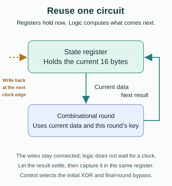
After a clock edge, the register presents its current value and the connected logic responds to that input. Gate delays mean the result is not correct instantaneously: it needs time to settle. At the next clock edge, the register captures the settled result as the starting point for the next round.
Combinational logic does not wait for clk to begin calculating. The clock determines when registers sample their inputs. In RTL, the calculation is typically expressed with assign, always_comb, or combinational submodules; storage belongs in always_ff at the rising edge. A correct formula can still fail at the target frequency if its logic path has not settled before the next capture.
Feedback does not mean encryption runs forever. Control enables updates during rounds and holds the state while ciphertext awaits acceptance. It tracks the round number and selects the initial XOR, the normal-round path, or the final-round bypass. Sections 12 and 13 will turn this explanation into an exact edge schedule.
Check your understanding: why is a datapath alone insufficient? The same circuit must do different work at different stages. It cannot independently know that this is the first round, the final round, or the time to hold a finished result.
2. Open the three areas: architecture and interface
Now open Figure 2. State Register and AES Round Datapath form the data area. Original Key, Working Round Key and Key Expansion form the key area. Controller FSM is the control area. This view exposes which values must be stored and which actions must be coordinated.
On a first pass, follow in_data → State Register → Round Datapath → State Register → out_data. Follow the key path on a second pass, and the dashed control lines on a third. The wires exist continuously, but not every register is written on every cycle.

One key-path convention matters in Figure 2: the initial XOR uses K0 and does not advance the working-key register. During round r, that register holds K[r−1]. The combinational expansion produces K[r], which feeds this round immediately and is captured with its result at the ending edge. “Next Round Key” means next relative to the stored old key; it is the key used by the round now being computed, not a key deferred for another round. Section 12 gives the exact edge table.
| Signal | Direction | Width | Meaning |
|---|---|---|---|
| clk / rst_n | Input | 1 each | Rising-edge clock / active-low synchronous reset |
| key_valid / key_ready | Input / output | 1 each | Key-channel handshake |
| key_data | Input | 128 | Original cipher key |
| in_valid / in_ready | Input / output | 1 each | Plaintext-channel handshake |
| in_data | Input | 128 | Plaintext block |
| out_valid / out_ready | Output / input | 1 each | Ciphertext-channel handshake |
| out_data | Output | 128 | Ciphertext block |
| busy | Output | 1 | Transaction remains outstanding, including output stalls |
A transfer occurs only at a rising edge with both valid and ready high. A producer holds valid and data while waiting. Key and plaintext are separate channels; section 13 defines which wins if both arrive together.
Read valid as the source saying “this item is available” and ready as the receiver saying “I can take it at this edge.” One party alone cannot complete a transfer. If in_valid is high while a busy core keeps in_ready low, upstream must keep offering the same plaintext rather than assuming it was consumed.
3. Separate the initial XOR from the ten rounds
The initial XOR, normal rounds and final round are stages of one AES-128 calculation. The controller must identify the stage to select both the correct datapath and the correct key.

Initial step: AddRoundKey with K0
Rounds 1–9:  SubBytes → ShiftRows → MixColumns → AddRoundKey
Round 10:    SubBytes → ShiftRows → AddRoundKey
K0 is the original key. The final round omits MixColumns. Calling the initial XOR “Round 0” is convenient for the controller, but it is not an additional full round.
4. Fix the byte mapping before writing logic
AES arranges sixteen bytes in a four-by-four state. ShiftRows and MixColumns use this arrangement. It is not an arbitrary drawing convention: a different mapping changes which bytes the transformations operate on.
The AES state has four rows and four columns. Bytes fill each column first:
       col0 col1 col2 col3
row0    B0   B4   B8  B12
row1    B1   B5   B9  B13
row2    B2   B6  B10  B14
row3    B3   B7  B11  B15
Our interface convention is B[i] = state[127 - 8*i -: 8], so B0 is state[127:120], B15 is state[7:0], and column 0 is state[127:96]. Equivalently, s[row][col] = B[4*col + row]. Use this mapping for plaintext, intermediate states, round keys, and output; do not infer it from a host CPU’s endianness.
5. Build a combinational round
Four transformations occur in order, but that does not require four cycles. Combinational logic can connect one transformation’s output directly to the next input. This architecture stores the result only at the round’s ending edge, completing one round per cycle.
The delays therefore share one path. Adding a register stage can shorten that path, but it also changes round timing, key timing and controller behavior. The number of source files does not determine the number of hardware cycles.
We have treated the round as one box; now open it. SubBytes changes byte values, ShiftRows changes their positions, MixColumns combines values within a column, and AddRoundKey incorporates the round key. These four operations form one combinational path. Four boxes in a drawing do not imply four clock cycles.

module aes_encrypt_round (
    input  logic [127:0] state_i,
    input  logic [127:0] round_key_i,
    output logic [127:0] state_o
);
// Transformation logic omitted; this is an interface sketch.
endmodule
This block has no clock. Its output settles after the combinational delay. A state register captures the result at the next edge; a diagram arrow does not imply an extra cycle.
6. SubBytes substitutes each byte

Each of the sixteen bytes passes through the same AES S-box mapping without changing position. For example, S-box(8'h53) = 8'hed. A 128-bit-wide datapath can instantiate sixteen byte-wide S-boxes in parallel.
Implementations include a complete combinational lookup or a logic circuit. Verify all 256 input values against the standard table. If you choose synchronous memory for the lookup, its read latency changes the round schedule used below.
“Lookup” describes an input/output mapping, not sixteen sequential software queries. Sixteen combinational S-boxes can transform sixteen bytes concurrently. A single shared S-box saves hardware but needs multiple steps, intermediate storage and byte selection; it changes the controller and the one-round-per-cycle schedule.
SubBytes supplies a nonlinear transformation. Fixed XORs and bit permutations cannot simply replace it. First reproduce the standard mapping exactly; only then compare different S-box implementations for area and delay.
The port declarations separate a full-state transformation from one byte’s mapping. These are interface fragments, not complete module implementations.
module aes_sub_bytes (
    input  logic [127:0] state_i,
    output logic [127:0] state_o
);

module aes_sbox (
    input  logic [7:0] data_i,
    output logic [7:0] data_o
);
Connect the standard plaintext’s first byte to the S-box
Use section 1’s plaintext and section 17’s key. Initial AddRoundKey gives B0: 00 XOR 00 = 00 and B1: 11 XOR 01 = 10. Here hex 10 means decimal sixteen. Sixteen XORs produce 00102030405060708090a0b0c0d0e0f0.
In the standard S-box table, the high nibble selects the row and the low nibble selects the column. Input 00 maps to 63, 10 to ca, 20 to b7 and 30 to 04. The first column after SubBytes is therefore 63 ca b7 04. Substitution changes values, not positions. Mapping 00 to 63 is not another key XOR.
Treat the specified 256-entry S-box as a defined function here. Building its lookup circuit does not require first deriving finite-field inversion and the affine transformation. An advanced algebraic implementation must still match every table entry. Check initial XOR and Round 1 SubBytes in the laboratory before rearranging positions.
7. ShiftRows is a byte permutation

If every round only mixed the same four bytes within each column, columns would not interact. ShiftRows offsets the rows so that the following MixColumns combines bytes that came from different columns. That purpose makes the permutation easier to understand than memorizing four rotation amounts.
Rows 0, 1, 2, and 3 rotate left by 0, 1, 2, and 3 positions. Under our packed-vector convention, the output byte sequence is:
B0 B5 B10 B15 | B4 B9 B14 B3 | B8 B13 B2 B7 | B12 B1 B6 B11Byte values do not change. This operation needs wiring, not arithmetic or an additional register. Test it with sixteen distinct bytes so a row/column mistake is visible.
The fixed AES permutation does not need a variable shifter, and it does not move one position per clock. “Rotate left” is a description of the matrix transformation; the RTL connects each input byte to its specified output position.
Its interface preserves the 128-bit width:
module aes_shift_rows (
    input  logic [127:0] state_i,
    output logic [127:0] state_o
);
Read the first column again in the same round
Round 1 SubBytes has these four rows:
row0: 63 09 cd ba; row1: ca 53 60 70; row2: b7 d0 e0 e1; row3: 04 51 e7 8c.
Row1 rotates left one place and begins with 53. Row2 rotates two and begins with e0. Row3 rotates three and begins with 8c. Row0 stays put. The new column0 is therefore 63 53 e0 8c, not 63 ca b7 04. Reading all bytes column-first gives 6353e08c0960e104cd70b751bacad0e7. Check that column in the right-hand Round 1 ShiftRows matrix.
8. MixColumns uses finite-field arithmetic

Each output byte depends on all four input bytes in that column. Changing one input byte can therefore affect several output bytes; together with ShiftRows, later rounds spread that influence further. The operation remains reversible: it is not an average or a hash that discards information.
For one column {a0,a1,a2,a3}, compute:
y0 = 2*a0 ^ 3*a1 ^   a2 ^   a3
y1 =   a0 ^ 2*a1 ^ 3*a2 ^   a3
y2 =   a0 ^   a1 ^ 2*a2 ^ 3*a3
y3 = 3*a0 ^   a1 ^   a2 ^ 2*a3
Here multiplication is in GF(2^8), with reduction polynomial x^8 + x^4 + x^3 + x + 1. It is not integer multiplication. Multiply by two with xtime; multiply by three with xtime(x) ^ x.
function automatic logic [7:0] xtime(input logic [7:0] x);
    return {x[6:0], 1'b0} ^ (8'h1b & {8{x[7]}});
endfunction
Examples: xtime(57)=ae, xtime(ae)=47, and column db 13 53 45 becomes 8e 4d a1 bc (hex). ShiftRows moves bytes between columns; MixColumns mixes bytes within a column.
The full-state module applies the column function four times. AES has no MixRows step.
module aes_mix_columns (
    input  logic [127:0] state_i,
    output logic [127:0] state_o
);

module aes_mix_one_column (
    input  logic [31:0] column_i,
    output logic [31:0] column_o
);
Derive 5f 72 64 15 from 63 53 e0 8c
A GF(2⁸) element fits in one byte. Addition is XOR; multiplication reduces by this section’s polynomial. It is not carry-based integer addition. First calculate multiplication by 2 with xtime: 63→c6, 53→a6, e0→db and 8c→03. The last two had bit7=1; for example xtime(e0)=c0 XOR 1b=db.
Multiplication by 3 XORs that result with the original byte, giving a5,f5,3b,8f. Substitute into the four column equations:
y0=c6 XOR f5 XOR e0 XOR 8c=5f
y1=63 XOR a6 XOR 3b XOR 8c=72
y2=63 XOR 53 XOR db XOR 8f=64
y3=a5 XOR 53 XOR e0 XOR 03=15
Each output uses all four inputs from this same column. Calculate the other columns independently to obtain section 17’s full MixColumns state. Advance one laboratory step and verify column0=5f 72 64 15. A more scrambled appearance is not a correctness test.
9. AddRoundKey is XOR
The preceding transformations follow fixed public rules. AddRoundKey incorporates this round’s key, making the result depend on the selected key. Its simple arithmetic does not make the key path less important to verify.

state_o = state_i ^ round_key_i. For one byte, 53 ^ ca = 99 in hex. Matching the state and key byte order matters just as much as choosing the right round key.
All 128 bit pairs can be XORed concurrently; there is no carry chain and no need for 128 cycles. The practical trap is often a key from the wrong round, rather than the XOR itself.
The interface makes that second input explicit:
module aes_add_round_key (
    input  logic [127:0] state_i,
    input  logic [127:0] round_key_i,
    output logic [127:0] state_o
);
10. Share the final-round datapath
Round ten omits MixColumns but still performs SubBytes, ShiftRows and AddRoundKey. This is an AES-128 requirement. Calling an unchanged normal-round function again would compute the wrong result.

The final round uses K10 and bypasses MixColumns. A shared physical datapath can compute SubBytes and ShiftRows once, then select either the MixColumns result or the bypass before AddRoundKey. Separate boxes in a functional diagram do not require duplicate hardware.
A bypass does not remove the need to advance to K10. Using K9 in an otherwise correct final-round path still produces the wrong ciphertext. Check path selection and key selection separately rather than relying on a counter reaching ten.
11. Expand keys with an explicit word order

Split the current key into four 32-bit words, {w0,w1,w2,w3}, most significant word first.
Distinguish the key you must preserve from the key that advances through the calculation. If a single register is overwritten through expansion, it contains K10 after encryption. Starting the next block from that value would be wrong. Our architecture preserves K0 separately and restarts the working-key sequence for every block.

temp = SubWord(RotWord(w3)) XOR Rcon(round)
w4 = w0 XOR temp
w5 = w1 XOR w4
w6 = w2 XOR w5
w7 = w3 XOR w6
next_round_key = {w4,w5,w6,w7}
RotWord({a,b,c,d})={b,c,d,a} and SubWord applies four S-box substitutions. Rcon is a 32-bit word with the constant in its most significant byte. For rounds 1–10:
01000000 02000000 04000000 08000000 10000000
20000000 40000000 80000000 1b000000 36000000
There are eleven keys including K0, produced by ten expansion steps. Our on-the-fly design keeps an original-key register and a separate working-key register. Reload K0 for every block. Precomputing all keys is another option; the key data alone then requires 1408 bits.
Key expansion takes a round index from 1 through 10:
module aes128_key_expand_step (
    input  logic [127:0] key_i,
    input  logic [3:0]   round_i,
    output logic [127:0] key_o
);
Derive K1 and reconnect it to round one
The standard key has w0=00010203, w1=04050607, w2=08090a0b and w3=0c0d0e0f. RotWord(w3)=0d0e0f0c. Four S-box lookups give d7ab76fe. Round 1 Rcon=01000000 makes temp=d6ab76fe.
Then w4=00010203 XOR d6ab76fe=d6aa74fd; w5=04050607 XOR d6aa74fd=d2af72fa; w6=08090a0b XOR d2af72fa=daa678f1; w7=0c0d0e0f XOR daa678f1=d6ab76fe. These four words form K1, not four keys for different rounds.
Round 1 MixColumns column0 was 5f726415. XORing it with K1’s first word d6aa74fd gives 89d810e8. The other three columns use the corresponding K1 columns to finish round one. Initial XOR used K0; this XOR uses K1. Section 12 captures round-one output and K1 at E2. The laboratory splits it into visible microsteps; each Next click is not one RTL clock.
12. Follow one block across clock edges
Iterative means reusing the same round circuit. A state register holds the previous result and feeds it into that circuit again. This avoids ten separate round datapaths, but this core advances only its one current block at a time.

Assume the key is already loaded. E0 is the plaintext handshake edge. Values in this table describe the registers immediately after each rising edge. Round logic and key expansion are combinational.
| Edge | Register update | Working key | FSM after edge |
|---|---|---|---|
| E0 | Capture plaintext; reload K0 | K0 | ROUND_0 |
| E1 | State XOR K0; set counter to 1 | K0 | NORMAL_ROUND |
| E2–E10 | Complete rounds 1–9 using the newly expanded key | K1–K9 | FINAL_ROUND after E10 |
| E11 | Complete round 10; state holds ciphertext | K10 | OUTPUT_HOLD; out_valid=1 |
| E12 or later | Transfer output when out_ready=1 | Hold | READY |
| E13 or later | Earliest next plaintext acceptance | Reload K0 | ROUND_0 |
Input acceptance to output-valid latency is 11 cycles. The earliest output transfer is E12, and the unstalled input interval is 13 cycles. This simple core does not accept the next input on the output-transfer edge. With no stalls or key changes, throughput is 128 × f_clk / 13 bits/s; obtain the achievable frequency from synthesis and timing analysis.
The state register directly drives out_data while held in OUTPUT_HOLD. Adding another output register would require revisiting the schedule.
// Conceptual NORMAL_ROUND fragment; helper functions are omitted.
state_reg     <= normal_round(state_reg, next_round_key);
round_key_reg <= next_round_key;
next_round_key is the combinational expansion of the current working key for the current round. Using round_key_reg as the round function’s key here would read the old key: nonblocking assignments do not update their right-hand operands in sequence. The final round similarly uses K10 expanded from K9.
Both the data transformation and key expansion must settle within the cycle. This version uses sixteen datapath S-boxes plus four independent key-expansion S-boxes. Sharing fewer S-boxes or using registered memories changes latency and control; “one round per cycle” is an architectural choice, not a property of AES.
13. Make the controller contract unambiguous
The FSM is the core’s progress record. A round counter alone cannot distinguish “no key yet,” “waiting for plaintext,” and “ciphertext finished but not accepted.” State identifies the stage; the counter identifies the round within computation. Together they determine datapath selection and register updates.

| State | Responsibility |
|---|---|
| NO_KEY | Wait for a key handshake |
| READY | Accept a replacement key or plaintext |
| ROUND_0 | Initial AddRoundKey |
| NORMAL_ROUND | Rounds 1 through 9 |
| FINAL_ROUND | Round 10 without MixColumns |
| OUTPUT_HOLD | Hold ciphertext until its handshake |
Use the following policy consistently in RTL and the testbench:
key_ready = rst_n && (fsm == NO_KEY || fsm == READY).in_ready = rst_n && (fsm == READY) && !key_valid. Key loading wins if both valid signals are high. The plaintext producer holds its request until a later handshake.out_valid = rst_n && (fsm == OUTPUT_HOLD). No new key or plaintext is accepted during computation or output holding.- busy stays high from ROUND_0 through OUTPUT_HOLD, including backpressure.
- On a rising edge with rst_n low, clear the original key, working key, state and counter; return to NO_KEY and cancel the outstanding transaction. Ready and valid are low during reset. Reload a key after reset.
A synchronous reset clears registers only at a clock edge. This educational reset policy is not a claim of validated product-level zeroization or side-channel protection.
Giving key loading priority avoids accepting a plaintext with the old key on the same edge as its replacement. The waiting plaintext is not lost: its producer retains valid and data until the later handshake.
14. Hold output under backpressure
Judge a handshake at the agreed rising edge, not merely because valid and ready were high somewhere in the waveform. Valid says the item is available; ready says the receiver can accept it. Both must be high at that sampling edge.
When out_valid=1 and out_ready=0, keep out_valid high and out_data unchanged. Remain in OUTPUT_HOLD. Once both are high at a rising edge, count exactly one output transfer and return to READY.
The same producer rule applies to key_data and in_data while their respective valid signals await ready. A waveform crossing between edges is not a transfer. In verification, count transactions only at handshake edges.
For the sensor, a stalled consumer does not require another encryption. Stop updating the state register and keep the finished ciphertext. Busy remains high because the transaction is outstanding. Treating busy as “round logic is calculating” could allow a new input to overwrite that result.
For a concrete delayed transfer, suppose downstream first accepts at E14. The core returns to READY after E14 and can accept the next plaintext at E15, absent a competing key request. E11 creates valid after its update; E12 is therefore the earliest output-transfer edge.
15. Read hierarchy as function, then choose sharing

A practical first implementation contains a controller, original and working key registers, a state register, one shared round datapath, and one key-expansion step. The normal/final branches above express functions; use a bypass selection to share their SubBytes, ShiftRows and XOR logic physically.
The hierarchy assigns responsibilities: control owns timing, the round owns state transformation, and expansion owns the next key. Give each block independently testable inputs and outputs so you can locate the first mismatch.
Choose physical sharing when instantiating those functions. Separate normal and final datapaths may add unnecessary area. Sharing fewer S-boxes may save area but requires more scheduling; it cannot retain the original cycle table unchanged.
16. Implement in small steps
Make failures easy to locate before chasing maximum throughput. Establish byte ordering and tests for the four transformations, then integrate them. Keep each earlier test as the design grows so new wiring cannot hide an old failure.
- Fix packed-byte ordering and verify S-box, ShiftRows, xtime and MixColumns separately.
- Combine a normal round, then add the final-round bypass.
- Check key expansion independently before connecting it to the round logic.
- Add the state register, counter and FSM using the edge table.
- Add key arbitration, output holding and reset behavior; verify consecutive blocks.
The numerical checks begin with all 256 S-box inputs, then sixteen distinct bytes through ShiftRows. Follow with xtime, MixColumns, a normal round and the final-round bypass. Verify key expansion independently before joining it to registers and control.
Finally, process two transactions with one key. The first shows that starting from K0 works; the second checks that the working key reloads K0 instead of continuing from K10. Add simultaneous key/plaintext requests, backpressure and reset to test the interface contract too.
17. Debug the first mismatch
Before debugging ciphertext, check the implementation contract:
- State byte mapping is explicit.
- SubBytes performs sixteen byte substitutions.
- ShiftRows only permutes bytes.
- MixColumns operates independently on four columns.
- AddRoundKey is a 128-bit XOR.
- Key expansion produces K1 through K10.
- Rounds 1 through 9 include MixColumns.
- Round 10 omits MixColumns.
- Output remains stable while
out_valid && !out_ready. - The FIPS 197 known-answer vector passes.
Use this known-answer case from the original NIST FIPS 197 Appendix C.1:
Key        = 000102030405060708090a0b0c0d0e0f
Plaintext  = 00112233445566778899aabbccddeeff
Ciphertext = 69c4e0d86a7b0430d8cdb78070b4c55a

After initial XOR : 00102030405060708090a0b0c0d0e0f0
Round 1 SubBytes  : 63cab7040953d051cd60e0e7ba70e18c
Round 1 ShiftRows : 6353e08c0960e104cd70b751bacad0e7
Round 1 MixColumns: 5f72641557f5bc92f7be3b291db9f91a
Round Key 1       : d6aa74fdd2af72fadaa678f1d6ab76fe
Round 1 result    : 89d810e8855ace682d1843d8cb128fe4
Compare intermediate values in the packed order from section 4. The first divergence tells you which transformation to investigate; a final-ciphertext mismatch alone does not.
| Test | Failure it can expose |
|---|---|
| All 256 S-box entries | Missing/wrong lookup entries or latches |
| Sixteen distinct bytes through ShiftRows | Row/column or packed-byte confusion |
| Every round state and K1–K10 | Stale key, Rcon placement, counter errors |
| Two consecutive blocks with one key | Starting the second block from K10 |
| Key and plaintext valid together | Incorrect key-priority behavior |
| Hold out_ready low, then release | Lost, overwritten or duplicated ciphertext |
| Reset during computation and output hold | Stale output or missing key reload |
| Random blocks and keys against an independent model | Data cases absent from one known-answer test |
A scoreboard checks accepted and emitted transaction counts, order and ciphertext. Flush canceled expectations on reset and set a timeout so deadlock becomes a failure.
Numerical and transaction checks answer different questions. A known-answer test can detect incorrect ciphertext without detecting duplicate delivery. Counting transfers alone can accept the wrong ciphertext. Both are needed for this lesson’s functional verification goal.
This core is a single-block encryption primitive. A message-level system still needs a suitable mode, nonce/IV rules, key management and integrity protection. Functional vectors do not establish resistance to power/EM leakage or fault injection.
18. Sources and scope
- NIST FIPS 197, updated 2023: state mapping (§3.4), field multiplication (§4.2), cipher (§5.1), and key expansion (§5.2). The update did not change the AES algorithm.
- Original NIST FIPS 197, 2001: Appendix C.1 supplies the known-answer case and intermediate values above. Use the updated standard for the specification.
- NIST examples with intermediate values: further reference cases.
The E0–E13 schedule, arbitration and reset rules belong to this teaching architecture; NIST does not prescribe this RTL interface.
Decryption, message-level modes, AXI/DMA and higher-throughput pipelines remain outside this core. Add them according to system requirements after the first design works. Side-channel and fault defenses require separate security validation; one known-answer vector cannot establish them.
References
- NIST FIPS 197: Advanced Encryption Standard: The authoritative byte-level AES algorithm reference.
MY ACADEMY · LESSON FILM
Lesson video
The film explains this lesson’s data path. After a section, return to the interactive exercise and change the input or fault conditions. The animation presents a teaching model; it does not replace RTL simulation.
Narration uses a synthetic voice. Both the interaction and animation have model boundaries; interpret results using this lesson’s sources and validation scope.
MY ACADEMY · RTL LAB
Operate AES: inspect every state transformation
Enter one 128-bit block and key. Stop at Round 1 ShiftRows and compare both matrices. Then reach Round 10 and check that MixColumns is omitted.
Matrices use the column-major layout of FIPS 197. Position [row, column] maps to input byte 4×column + row. Each step shows values before and after an operation. These algorithm microsteps do not claim one RTL clock each.
Evidence scope: a browser functional teaching model. Independent comparison uses browser Web Crypto. No RTL simulation, synthesis, formal proof or side-channel testing is performed.
Independent comparison uses the first Web Crypto CBC block with IV=0: C0=AES_K(P0 XOR 0)=AES_K(P0). We compare only its first 16 bytes; a later padding block does not change the first. This checks single-block AES, rather than implementing a message mode in this lab.
Before operation
After operation
Inspect blocks, schedule and round keys
Output handshake: valid / ready
At OUTPUT, the output remains stable. Set ready, then sample an edge to record acceptance. Changing ready alone does not accept data. This handshake is a separately defined teaching interface.
Transfer exercise: may RTL clear output_valid or overwrite the result before downstream is ready? State the hold rule in plain language: unless reset cancels the transaction, valid and data remain stable until a handshake. SVA syntax is an optional next exercise.
Learning guide
Cryptographic RTL Design
Open the course outline → · Progress counts published lessons only
Prerequisites
- AES round operations and synchronous logic
What I learned
- Partition AES into datapath and control
- Define valid/ready behavior
- Keep byte ordering consistent